Influence of Friction Resistance on Expression of Superelastic Properties of Initial NiTi Wires in “Reduced Friction” and Conventional Bracket Systems
- Natalie Reznikov naoree{at}gmail.com1
- Gilad Har-Zion gilad9{at}012.net.il2
- Idit Barkana iditbarkana{at}yahoo.com2
- Yosef Abed abedy{at}cc.huji.ac.il2
- Meir Redlich mredlich{at}bezeqint.net2
Abstract
Objectives. The aim of this study was to assess the influence of resistance to sliding on expression of superelastic properties of NiTi wires.
Methods and Materials. A three-point bending test was performed for 0.014 NiTi wire engaged in self-ligating (Damon, SmartClip, In-Ovation) and conventional brackets (Victory) ligated with regular and reduced friction modules (Slide). The wire was deflected in the buccal direction and allowed to straighten. The maximum load, unloading plateau and unloading capacity were registered.
Results. The lowest activation load was required in the active self-ligating group (In-Ovation  N) and reduced friction module group (Victory/Slide
  N), followed by the passive self-ligating systems (Damon
  N, SmartClip
  N). Higher activation load was obtained in the conventionally ligated group (Victory/module
  N). Unloading plateau phase with the load magnitude ranging from
  N (In-Ovation) to
  N (Slide) was distinct in all groups but one (Victory).
Conclusions. Higher friction at flanking points reduces the net force delivered by the wire. Unloading plateau phase of NiTi load-deflection curve disappears in the conventionally ligated group thus indicating to an incomplete expression of NiTi superelastic properties. A rigid passive bracket clip amplifies resistance to sliding in an active configuration and produces a permanent deflection of the wire.
1. Introduction
Orthodontic treatment aims to relocate malpositioned teeth within the jaws using an application of mechanical forces. These forces are created by a variety of appliances such as wires, springs, elastics, and so forth. Activation of an appliance creates a measurable deflection and internal stress of the material.
Although little is known about the optimal orthodontic force [1], it is widely assumed that the optimal orthodontic tooth movement occurs under a small and continuous force. The force magnitude must overwhelm the biological threshold of 0.5–0.7 N (a value sufficient to cause tissue remodeling) and should not exceed a value of 2-3 N (a biological corridor) [2].
During the initial alignment stage of fixed appliance treatment, a clinician chooses a light, low-module archwire for a given
dental condition. Engaging the wire into brackets activates the wire and creates internal forces. Upon the activation, an
internal shear force drives wire straightening and application of force on teeth. This orthodontic force is a function of
the wire deflection, elastic modulus, crossection, and interbracket distance:
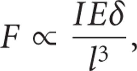 where F stands for the force, I for the momentum of inertia, E for the elasticity modulus, δ for the deflection, and l for the beam length.
The interbracket distance and deflection parameters (i.e., the degree of malalignment) are known and wire modulus and crossection are chosen by a clinician. Seemingly, since the parameters are identified, the orthodontic forces of a controlled magnitude and an accurate direction can be delivered to teeth. However, as the malalignment is being corrected, the wire deflection curvature flattens. As a result, the wire slides through the neighboring brackets. At this point, the important role of friction forces arises.
Friction is a ubiquitous force accompanying interaction of any two bodies. Kinetic friction acts during sliding of two solid surfaces in the direction opposite to that of motion. Static friction refers to a force parallel to two surfaces that exists even when the surfaces are not sliding.
Friction is defined by the following equation:
 where
where  stands for the friction force;
  denotes the normal (perpendicular to the contacting surfaces) force, which pushes one body towards another, and μ is the
friction coefficient, which depends on the surface composition and finish. Static friction coefficient is almost always greater
than the kinetic one [3].
Orthodontic tooth movement is not constant and it occurs at a very low rate and is sometimes called a pseudo static condition. A diversity of opinion exists in orthodontics about whether static or kinetic friction should be considered, or both.
A concept of friction force in orthodontics was presented in 1997 by Whitley and Kusy [4] and became widespread. Mathematically, friction resistance to sliding is described as an additive effect of classical friction,
binding, and notching. The equation is
 where RS is the net force retarding the tooth movement; FR may occur solely in a passive configuration (i.e., force exerted
by a ligating auxiliary times friction coefficient); BI and NO appear consequently in active configurations and can significantly
exceed FR. While notching NO is an extreme and undesirable condition, and pure friction resistance FR is rare in clinic (especially
during the alignment stage of the treatment), a combined effect of both FR and BI influences orthodontic forces exerted by
initial archwires.
When the wire bends against the slot wall, not only does the wire exert a force on the bracket, but, according to the third law of Newton, the slot wall exerts a force on the wire equal in magnitude and opposite in direction. As a result, any nonaxial wire deflection creates a normal force acting on the wire [5]. If the wire is deflected in the bucco-lingual direction, then both force vectors coincide—the normal force of the ligating auxiliary and the normal force originating from wire bending against the buccal aspect of the bracket. These two components, the ligature derived and the wire derived, multiplied by the coefficient of friction (2), comprise the total friction which impedes the wire sliding through the brackets as malalignment is being corrected. The ratio of two normal force components varies. The ligature derived normal force depends on a bracket design; the wire derived normal force depends on wire characteristics and deflection extent. In the case of working stainless steel wires, the wire-derived normal force component plays the major role even at tiny deflections, measurable only in laboratory conditions; the bracket-locking mechanism may demonstrate unexpected interaction with stainless steel wire (e.g., rigid passive clip of self-ligating brackets may significantly aggravate wire binding at deflections about 0.15–0.2 mm) [6].
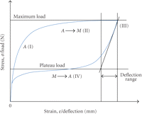
The state is quite different with low module wires at the initial stage of treatment. Widespread nickel-titanium wires, as opposed to stainless steel wires, do not demonstrate linear deflection/load dependency. NiTi alloy has a unique property of shape memory—a reversible, solid phase transformation known as a martensitic transformation. The alloy changes its crystal structure from austenite to martensite and vice versa as a response to a temperature or load change (Figure 1). This transformation results in a pseudoelastic behavior. When the strain exceeds a specific value, a martensitic phase is generated. At this stage (Figure 1, II) stress or load remains near constant for a wide range of strain, or deflection. Upon the load withdrawal, the martensitic crystal structure turns back into the austenite mesh (Figure 1, III) and the wire regains its original shape. Upon unloading, the load also remains constant but at lower values (unloading plateau, Figure 1, IV). A stress gap between the loading and unloading plateaus (hysteresis loop) represents an amount of stored energy which is spent on crystal mesh reorganization.
Stress-strain diagram for a self-memory alloy. (I) linear loading at austenitic phase; (II) loading plateau, martensitic phase transformation; (III) rapid linear stress decline on load withdrawal; (IV) unloading plateau, austenitic phase transformation. Comparison parameters of superelastic wire in three-point bending test: maximum load, N; plateau load, N; deflection range, mm.
NiTi orthodontic wire has a typical nonlinear recoverable deformation behavior and delivers biologically reasonable forces at a clinically applicable deflection range of several millimeters. For example, 0.014′′ Nitinol wire during unloading exerts a force of 1–2 N in deflection range of 0.5–5.0 mm [7, 8], which is consistent with the concept of the presumptive biological corridor [2].
The bending force of initial nickel-titanium wires is nonlinear, small and almost constant for a wide range of deflections; as such it is comparable in magnitude with ligation derived normal force in conventionally ligated systems [9].
The purpose of the present study is to assess whether the resistance to sliding as a function of ligation method affects the expression of mechanical characteristics of superelastic wires.
2. Materials and Methods
Among five bracket groups, there were three self-ligating brackets two passive: Damon2 (Ormco SDS, Glendora, USA), SmartClip
(3M Unitek, Monrovia, USA), and one active: In-Ovation (GAC, Bohemia, USA). Two types of ligated brackets were used: a conventional
bracket Victory-MBT prescription (3M Unitek, USA) with conventional elastomeric ligature (elastic o-modules, Sani-Ties Silver,
GAC International) and Victory-MBT prescription bracket with “Slide” low friction ligature (Leone America, Oxnard, USA. All
the brackets were with  -inch stainless steel slots, upper right central incisor.
Although there is a special archwire sequence, proposed by each manufacturer for each bracket system, a commonly used archwire was chosen for the study, NiTi 0.014 (GAC International), received in spool.
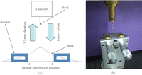
Three-point bending test in the bucco-lingual plane, simulating the first-order wire deflection (Figure 2), was performed using the Lloyd Materials Testing Machine, Lloyd Instruments Ltd, UK (Twin Column Testing Machine LR10K with
10 kN load cell). Two brackets of each group were mounted on the horizontal surface of the assembling device. The brackets
were arranged along a full-sized stainless steel guiding wire to prevent any slot misalignment, and then bonded with HighQ
Bond SE (self-etching dual cured permanent adhesive resin cement, BJM Lab, Israel). A double typical interbracket distance
( mm) was set between the flanking brackets. Passively engaged NiTi wire was connected to the load cell at its half way point
by means of a custom-made metal hook, without a bracket, since no wire sliding occurs at this site.
(a) three-point bending test scheme; (b) a photograph of the assembling device with two brackets mounted on its upper surface; the wire is engaged into the brackets and elevated to a given height.
The wire was elevated buccally to a height of 5.3 mm from the horizontal line (deflection, corresponding to 50°) during 10 seconds and then released. An exaggerated deflection was intended to mimic archwire behavior in severe crowding cases—a picture frequently seen in advertisements of self-ligating brackets manufacturers. This design aimed, primarily, to assess clip/module interaction with the activated wire, and secondly, to demonstrate if spontaneous wire unloading is possible at that extent of malalignment.
After releasing the active machine head pull, the unloading force exerted by the wire on the load cell was measured. The maximum loading force and constant unloading plateau values were recorded using NEXYGEN MT Materials Test and Data Analysis Software. The deflection range between the peak force and the plateau force on unloading was determined on the x-axis as a distance between the peak deflection and the point where the unloading graph slope approaches zero. A narrow deflection range is typical for the superelastic behavior, which can be fully accomplished when the wire unloads unrestrictedly. The experiment was performed in 5 replicas for every group, with 5 consecutive readings taken in each replica (25 measurements for each group). 50 brackets and 25 wire segments of 70 mm were expended. All the measurements were performed by N.R. (the first author). A random test sequence was developed to minimize learning curve influence on result precision.
The results between different groups of brackets were analyzed with the Bonferroni multiple-comparison tests model. The null
hypothesis states that no differences exist in load and range values among NiTi wires connected to various types of brackets.
Statistical significance was determined at the  level. Bonferroni adjusted t-test takes the number of comparisons (10 pairs in this study) as a divisor for the general P level to make each particular test more stringent and conservative.
3. Results
In all experimental groups, the deflected wire was capable of spontaneous straightening after machine head pull release.
In all experimental setups except for the Victory/module group, load-deflection curves typical for shape-memory alloys [8] were achieved (Figure 1). The following three parameters were taken for comparison: load on maximum deflection (N), unloading plateau load (N), and deflection range (mm) between maximum load and unloading plateau.
The maximum load represents the activation force applied by the load cell on the wire at the maximum elevation.
The unloading plateau represents the internal force delivered by the wire on the load cell during spontaneous unloading.
The third parameter—deflection range—denotes the unloading capacity. The narrower the deflection range is the fuller superelastic behavior of the wire is expressed.
According to the principles of superelasticity, an austenitic alloy transformation should occur on stress relief which is graphically expressed as a fast decline of load to a plateau value. In the Victory/module group, unloading was rather gradual and the phase transformation segment (Figure 1, III–IV) of the graph was shallow. Therefore, when the plateau phase was blurred, its estimation became unclear. Hence, the Victory/module group was excluded from the comparison by the plateau load and deflection range parameters.
In the passive self-ligating groups, residual permanent deformation was observed on withdrawn wire samples.
4. Discussion
This paper presents a simplified three-point model, in which the wire is actively elevated in the buccal direction at the middle point and then is allowed to unload passively. During both steps of the experiment the wire slides through the flanking brackets. Theoretically, the maximum load and unloading plateau values are determined by the wire stiffness and interbracket distance (1). Consistent with nonlinear superelastic behavior, these forces are almost constant for a broad range of deflections, including that of the experiment. Nevertheless, a significant intergroup difference was observed in the maximum load values, as well as in load/deflection graphic patterns.
In order to explain this phenomenon we describe two extreme conditions.
In the hypothetical situation of a totally frictionless system, the load decreases rapidly from the maximum load to the unloading plateau, immediately after the pull is released. While regaining its original shape, the wire delivers a constant force to the middle point. A graphical expression of this internal force is referred to as the unloading plateau (Figure 1).
In the other hypothetical state, consider an infinite friction force at the flanking brackets. As a result, no sliding is possible through the flanking points. The system is static either in a passive (straight) or active (deflected) configuration. Therefore, the force delivered to the middle point equals zero (Figure 3).
A flexible beam represented by a metal measure tape is held tightly on both of its ends. In order to pull the tape upwards an extra force is required to overcome the friction. Spontaneous straightening of the beam is not possible because its shear force is insufficient to overcome friction at the side points. Therefore, if no movement occurs at the side points, no force will be delivered by the beam at the midpoint.
Hence, the force generated by 0.014 NiTi wire in any bracket system should lie in the range between 2–3 N in a frictionless system and zero in an infinite friction system.
Spontaneous unloading of the wire is only possible when the internal shear force of the wire exceeds the friction force on the side points (Figure 4).
The NiTi 0.014 wire unloading scheme in three-point configuration. The side points are stationary and the midpoint is mobile. The forces acting in the system are indicated by the arrows; α designates the deflection angle.
This relation can be expressed by the inequality:
 where
where  stands for internal shear force of the wire at the midpoint;
  is the friction force at each of the side points; 2 is the coefficient which indicates that there are two points where the
friction force acts, and α is the deflection angle. In the described configuration, friction force
  at the side brackets depends on two normal forces (2): the ligation derived force and the wire derived force—a reciprocal force exerted on the wire by the bracket wall.
The means and standard deviations of the maximum load, plateau load, and deflection range for each group in the three-point bending test are summarized in Table 1.
In our experimental setup the wire was pulled nonaxially, in the buccal direction. At both flanking points the wire contacted the buccal aspects of the bracket slot, which were different in all investigated bracket types: a stainless steel rigid face in the Damon group, nickel-titanium pointed clips in the SmartClip group, a cobalt-chromium springy shield in the InOvation group, and a polyurethane surface in the Slide and the conventional module groups. All experimental parameters were the same except for the wire locking mechanism; therefore, the source of variation might be in the interaction between the deflected wire and the bracket's buccal aspect.
The binding configuration was emulated intentionally to assess the overlapping effect of classical friction and a reciprocal force exerted by the wire locking mechanism on the deflected wire. A ratio of these two components (corresponding to friction, FR, and binding, BI; (3)) was different in each group.
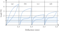
The typical loading/unloading loops obtained in this study for each group are represented in the Figure 5.
Load-deflection curves obtained in each experimental group are compared to the presumptive biologic corridor range (the two wide horizontal lines). (a) Conventionally ligated Victory bracket, (b) passive self-ligating brackets Damon and SmartClip, (c) active self-ligating bracket In-Ovation, (d) Victory bracket with reduced friction ligatures Slide. Note that in all but the first graph there is a distinct plateau phase.
Maximum load in each group equals the sum of the wire shear force (constant) plus the resistance to sliding at side points which is comprised of ligation derived and wire derived components (i.e., classical friction and binding).
In the case of the conventionally ligated brackets (Figure 5(a)) the maximum load has the highest value, reflecting higher ligation derived component. The unloading arm declines rapidly and almost linearly—no unloading plateau is discernable [10, 11].
In the passive self-ligating group (Figure 5(b)), the maximum load value is not much lower than in the conventional group. That high value can be conditioned by a sharp wire curvature at the side points, i.e., higher reciprocal force delivered on the wire by the rigid clip. The unloading arm of the graph drops instantly after a pull release and the unloading plateau phase is well expressed.
In the active self-ligating group (Figure 5(c)) the maximum load has the lowest value among all groups—its flexible active clip is capable of minor deflections together with the wire and exerts lower reciprocal force on the deflected wire. The load decreases rapidly to a distinct plateau.
The reduced friction module group (Figure 5(d)) demonstrates a low maximum load value (insignificant difference with the active self-ligating group). The plateau phase is well expressed, the unloading part of the graph decreases more gradually.
In all groups except for the conventionally ligated bracket group the plateau phase was distinct. Importance of this plateau phase cannot be overestimated in a view of the fact that a low and constant force actually stands behind tooth movement once a wire is activated.
It could be mistakenly concluded that higher friction resistance prevents tooth overloading by absorbing excessive forces. As friction requires additional force upon activation, it also consumes a considerable part of the shear force upon unloading. Hence, there is no “low friction/light forces versus high friction/high forces”; instead there is “low friction/light forces versus high friction/insufficient forces”.
As the deflected wire exerts pressure in the labial direction during engagement, the flanking ligating auxiliaries resist, deflect, or stretch in the corresponding direction.
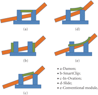
Some inevitable interaction patterns between wires and ligation auxiliaries noticed in the course of the experiment are schematically illustrated in Figure 6.
In the passive self-ligating bracket groups (Damon, SmartClip) the wire displayed a sharp curvature touching its clip. Postexperimental visual examination of the wire revealed a permanent deflection of the wire (notching). In some SmartClip experiments the wire spontaneously disengaged from the mesial wing of the bracket.
An active clip of the In-Ovation bracket has an ability to deviate slightly in the buccal direction, thus reducing the deflection curvature and increasing the beam length [6]. Consequently, the clip exerts lower reciprocal force on the deflected wire. Residual deformation was not observed on withdrawn wire samples. However, in some experimental setups a permanent distortion of the bracket clip was revealed.
Both Slide ligature and a conventional ligature are made of polyurethane and allow the wire to emerge out of the slot thus reducing the deflection curvature. However, the conventional module was exceedingly stretched and exerted a considerable normal force back on the wire thus increasing friction resistance.
Another source of the intergroup differences may be related to the surface elementary composition and the different coefficients of kinetic friction which are higher for polyurethane (conventional modules, “Slide” reduced friction ligatures) as opposed to metals (self-ligating brackets' clips) [12]. It may explain the wider deflection range in the Slide group.
Merely mechanical aspects were evaluated in this in vitro model. Biological resistance, mastication forces, wear of materials, and wet environment impact the aforementioned calculations and should be taken into account for justified clinical extrapolation of the study results.
5. Conclusions
-
(i) The expression of superelastic properties of NiTi wire is affected by the specific ligation method.
-
(ii) The unloading plateau disappears in the conventionally ligated group due to interferences between the normal pressure of the modules and the unloading pattern of the superelastic wire.
-
(iii) The higher friction resistance, either due to module pressure or because of clip-exerted reciprocal force, consumes a significant fraction of the unloading force, thus reducing the force delivered by the wire.
-
(iv) The lower friction impact allows a more precise approximation of the wire delivered force. The force level appropriate for a specific clinical situation can be obtained by varying diameter of the superelastic wire.
- Received May 26, 2009.
- Revision received August 2, 2009.
- Accepted September 8, 2009.
- © 2010 Natalie Reznikov et al.

