Biomechanics and force system of butterfly arch: A device for three-dimensional controlling of upper molars
- Alireza Nikkerdar, Private Practitioner, No. 17 Sepehr building, Sepand St., Ajudanieh, Tehran, Iran. Email: tec_341{at}yahoo.com
Abstract
There are numerous intra-oral appliances that are used for many purposes in orthodontic practice. Some popular instances include those for anchorage preservation, distalizing plates, and expansion appliances. In maximum anchorage extraction cases, which are serious challenges for orthodontists, none of intra-oral devices can preserve the anchorage precisely. Butterfly arch with its unique design, configuration, and biomechanical properties is introduced here as a device that could enhance the posterior anchorage meticulously. In addition, there are several advantages mentioned here to present the importance of the appliance to preserve the vertical and transverse dimensions as well.
Introduction
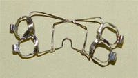
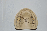
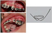
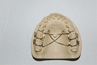
Transpalatal arch (TPA) or palatal bar (PB) is a device that has been used for many years in different clinical situations (Figure 1) either with fixed or removable types; the appliance is usually made of a stiff stainless steel wire with an omega loop in center.1⇓⇓⇓⇓–6 One of the most frequent applications of PB is considered to be benefits for anchorage unit’s enhancement; however, this idea has not been confirmed by new articles. Zablocki et al.7 pointed out that the PB neither preserves the anchorage nor the vertical dimension during orthodontic treatment. By using finite element simulation, Kojima and Fukui8 evaluated the stress level in periodontal ligament (PDL) in the presence and absence of PB; they observed no difference between the control group and the group with PB during space closure stage. The reason is quite simple. The failure of upper lingual appliances to preserve the anchorage is because of the inability to resist against the forces that apply perpendicular to its long axis. If a beam with a small cross section attaches firmly to a point and if a force even with a slight magnitude applies on the other free side, the beam rotates simply around the point of attachment with almost no significant resistance (Figure 2). Butterfly arch (Figure 3) comprises a 0.036″ stainless steel wire and four molar bands that form a rigid framework with high resistance against distortion and is introduced here as an appliance that could preserve the posterior anchorage with simultaneous controlling of vertical and transverse dimensions.9
Illustration of a possible anchorage loss phenomenon and how a mesially directed force tends to replace first molars when a transpalatal arch is in place.
Background
Anchorage loss
In a maximum anchorage situation, anchorage loss happens, more or less due to the creation of a reactive force as a result of anterior teeth retraction during space closure. This appears in two distinct forms: (1) in first order because of mesial-in rotation of posterior teeth, especially first molars when the reactive forces apply from buccal surface related to the centers of resistance; therefore, widest part of teeth encroaches the extraction space, and (2) in second order, as the consequence of tip-forward moment that exerts on posterior anchorage units, these teeth encounter “dumping effect” that leads to more anchorage loss. These two effects are main mechanisms of anchorage loss occurrence when mesially directed force tends to loosen the anchorage unit. It should be reminded that the manifestation in the form of either mesial-in rotation or dumping is because the mesially directed force is applied at the buccal side of the anchorage teeth.
Biomechanical principles
The biomechanics of butterfly arch are based on five principles regarding its unique design:
-
The principle of using tensile strength.
-
The principle of using tongue function.
-
The principle of creating reactive forces.
-
The principle of three-dimensional (3D) interactions.
-
The principle of using short segments.
The principle of using tensile strength
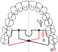
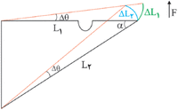
The best form of resisting against mesially directed force of anterior retraction in anchorage units is to transfer it into the form of axial loading, either compression or tension. Tensile strength of wires that we use in orthodontic practice is too high even in small, round cross-sectional wires. However, when a mesially directed force exerts on one end of a PB, the resultant of intrinsic forces is equal to 0, meaning there is no axial loading. Therefore, connecting left and right sides of the dental arch in molar area do nothing with anchorage reinforcement at all. If using the anchorage units of the other side of the arch is desired, somehow there must be some kind of establishment of “tension” in the connecting wire or bar. In butterfly arch, when a force that tends to displace the teeth of anchorage units applies, tension rises in all cross sections of the connecting oblique wire known as “bracing unit” (red segment in Figure 4). This would create an additional component to counteract mesially directed force. Mathematically, it could be proven by the following equations (Figure 5)
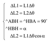
Because cos α < 1 → ΔL2 < ΔL1 →, there is a differential length change (H − H′) which shows tension.
Force system of a butterfly arch when a mesially directed force (F) applies on the left side of the picture dealing with resistance forces (R) of posterior teeth and bracing element (red segment).
Schematic and exaggerated illustration of the role of tension in a bracing element. F: mesially directed force, L1: length of the bar, L2: length of bracing system, Δθ: angular change which is very small, ΔL1: linear change at the present of bracing element, ΔL2: linear change when bracing element is not active and whole system is under rotation to H point, and H − H′: differential length change in L2 when tension created.
Principle of using tongue function
A wide pentagonal area, which is called here as “tongue trapping area” (often with acrylic coverage), could trap and direct the tongue pressure during functions (swallowing, speech, and chewing). With respect to the center of resistance of upper molar segments, which is closer to upper first molars, the wider part of tongue trapping area is located behind the center of resistance, and therefore, perpendicular tongue pressure against palate creates a high level of force on that area which tends to tip the crowns of upper first and second molars distally (Figure 6). The vertical component of this force, however, could control the vertical dimension very well.
The principle of 3D interactions
-
1. Interaction of vertical and horizontal dimensions.
Figure 7(a) shows the effect of a force on an object that is displaced by a drag force (F) in a distinguished direction (D) with a constant velocity if we eliminate the role of friction. Figure 7(b) illustrates a condition when a perpendicular force (Fv) applies on the moving object. If we need to maintain the original velocity, we have to increase the drag force to the extent that overcomes the additional vertically directed force. The same story is true for the butterfly arch when the tongue presses the tongue trapping area against palate during function. This vertical component of tongue force could affect the inappropriate reactive mesially directed force of anterior retraction and therefore could enhance anchorage in anteroposterior plane.
-
2. Interaction of transverse and horizontal dimensions.
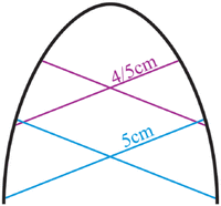
The rigidity of butterfly arch is considerably high. It is made of stiff stainless steel wire, and soldered joints create short segments that increase total rigidity of the framework of the appliance markedly. If this rigid apparatus encounters anchorage loss, the diameters have to be shortened inevitably (Figure 8) and “butterfly wing effect” occurs (Figure 9). This effect happens when a butterfly closes its wings and results in diminution in width. The high rigidity of the arch withstands this phenomenon because a huge force is needed to distort the multiplication sign-like framework.
Mesial movement of the appliance is accompanied by reduction in the width (d1 < d2); the rigidity of the appliance prevents butterfly wing effect.
The principle of creating reactive forces
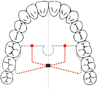
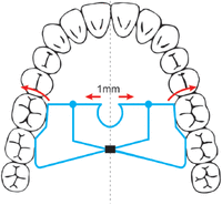
Regarding causative factors of anchorage loss, there are some components to neutralize mesial-in rotation and mesial tipping of the first- and second orders, respectively, so establishing a mechanism for applying reactive forces in the form of mesial-out and tip-back moments is essential for anchorage control. Mesial-out moment is created by 1-mm preactivation (0.5 mm each side) with opening of omega loop before placing of the appliance (Figures 10 and 11). This expands the inter-molar width slightly and usually remains until removing the butterfly arch in finishing stage. By reaching the settling phase, the inter-molar width would return to its original dimension. As mentioned earlier, the tip-back moment is created by tongue pressure against the tongue trapping area. It does not mean that the axial inclinations of the upper molars essentially change to more upright position. However, preservation of their inclinations mesiodistally, without any bodily movement, is enough to say that controlling of anchorage is quite successful.
The principle of using short segments
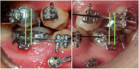
The essence of accurate application of butterfly arch is high rigidity for either preservation of transverse dimension or stabilization of the system and prevention of distortion. To preclude long lever arms and huge bending moments at soldering areas due to tongue function during mastication, we must avoid long segments as far as possible. Therefore, soldering points (green arrows in Figure 3) all over the framework are made to increase the total rigidity of the appliance effectively. These soldered joints must be bulky enough not to be broken when mechanical stress exerts.
Clinical indications of butterfly arch
-
Maximum anchorage cases with/without vertical discrepancy such as severe class I crowding and bimaxillary dentoalveolar protrusion.
-
Open bite correction within the scope of orthodontic treatment with premolar extractions.
-
To treat children with vertical maxillary excess instead of long-term headgear therapy; however, long-term stability is unclear. Combination of butterfly arch therapy while tongue trapping area is 4 mm away palatal mucosa with progressive grinding of deciduous teeth might be more appropriate for maintaining vertical dimension.
-
Full-cusp class II patients undergoing orthodontic camouflage in which maximum anchorage is required. In cases with vertical discrepancy, the appliance could provide an appropriate control on both horizontal and vertical dimensions.
-
Full-cusp class II subdivision cases.
-
Cases that underwent orthodontic/orthopedic expansion via banded hyrax. Tolerating the expander during retention phase is uncomfortable for the patients. In such cases, the hyrax-type banded expander could simply replace by butterfly arch with its specific design for this purpose (Figure 12). High rigidity of the appliance would maintain gained results properly.
-
By choosing segmental/sectional mechanics for closing the space or intrusion of anterior segments, the need for initial leveling and alignment of first and second molars, which is problematic with the side effect of second molar extrusion resulting in downward and backward rotation of mandibular plane, increasing gumminess, and clockwise rotation of occlusal plane, could be possibly decreased. However, there must be no evidence of posterior crossbites and severe posterior malalignment. This advantage would greatly enhance the effectiveness and efficiency of the treatment through less time-consuming process with no hazard of molar extrusion. With respect to all other factors, we can immediately extract the premolars and initiate applying extraction mechanics (Figure 13).
-
High versatility. Auxiliaries such as hooks and loops can be added and soldered to the butterfly arch (Figure 14). The usual cases that need auxiliaries are impacted canines and teeth with severe rotations. High resistance against mechanics that tend to create occlusal plane cants is one of the best examples. Removable type of butterfly arch, which will be presented in future, would increase the versatility of this kind of treatment much more.
Butterfly arch is well-suited to segmental/sectional mechanics with no need for initial leveling and alignment of posterior segments.
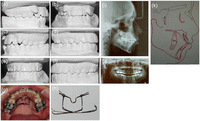
Regarding distinct advantages of butterfly arch, a maximum anchorage case is presented as follows (Figure 15).
Patient M.A. 16 years old, with a class I severe crowding problem: (a–f) study models before and after treatment; (g, h) butterfly arch when it is in place and when it is removed, respectively; (i, j) lateral cephalogram when the butterfly arch is in place; and (k) cranial base superimposition shows excellent control of anteroposterior and vertical dimensions during treatment although a little vertical growth is evident.
Discussion
Some conventional appliances that are used for anchorage reinforcement are as follows: headgear, TPA, Nance appliance, intra-osseous plates, and screws. Headgear is an extra-oral appliance that applies a distal force to maxillary first molars. It is quite dependent on patient’s cooperation regarding huge external apparatus which is prone to breakage. TPA and Nance appliance are good for tooth movement and rotation control, but because of biomechanical weaknesses, as mentioned earlier, anchorage preservation is compromised. Mini-screws can preserve anchorage pretty well. However, dislodgement, cost, undesirable vertical component, and difficulties of placement are their disadvantages. Mini-plates offer the most appropriate method of anchorage preservation and also intrusion, but they are expensive and need extra surgery with same inappropriate vertical component similar to mini-screws.
Although butterfly arch possesses numerous distinct advantages, however, if anchorage value and PDL stress distribution of the teeth of reactive unit are the same, and if an equal activation of right and left closing loops is performed, the result might be a mesial movement of whole system as the effect of a huge reactive force of anchorage loss without any intervention of bracing units of butterfly arch. This is usually rare due to special characteristics and mesiodistal position of anchorage teeth such as root morphology and length, root divergence and torque, level of teeth, and their inclinations. Furthermore, amount of activation is not quite the same which leads to unequal distribution of stress in PDL. These factors make difference in one side as compared to another, so bracing units are active most of the time in any side with greater mesially directed force or the side with weaker anchorage value. This side has an advantage to take the anchorage unit of the other side. If there is any problem with banding of second molars, it is possible to bond a mesh pad at palatal surface and solder the appliance as before. Breakage is uncommon; however, strengthening the joints is essential for preventing the appliance from distortion and breakage.
The action of vertical dimension on anteroposterior position of anchorage teeth, which is induced by tongue pressure, is similar to muscular anchorage of pterygomasseteric sling. In such conditions, the force magnitude is relatively high and the direction is almost the same. In addition, differential moment, which is created due to application of maximum anchorage mechanics, possesses vertical side effects that can be neutralized by similar aforementioned mechanism of tongue function on tongue trapping area. First molar area has a prominent role in precise and desirable application of butterfly arch as a focal point. The first reason is due to its design for accepting the preactivated expansion and tip-back moments. The second reason is the important role of transseptal fibers of second premolars in 3D following first molars when such intentional forces are applied from the appliance of first molars. For better control, it is appropriate to ligate the anchorage teeth whenever possible, more specifically first molars with second premolars.
Conclusion
Mechanical principles were described before, and they are new and unique and could be used for 3D preservation of upper anchorage teeth effectively. Expressions such as bracing systems and units, tongue trapping area, and butterfly wing effect are special mechanical characteristics of butterfly arch, and all of them are involved in 3D controlling of posterior anchorage units. The appliance has different shapes and configurations in various clinical situations. For better evaluation of clinical advantages of the butterfly arch, more study and practice should be performed to understand its influence on 3D controlling of upper molar’s positions.
Article Notes
-
Declaration of conflicting interests The authors declare that there is no conflict of interest.
-
Funding This research received no specific grant from any funding agency in the public, commercial, or not-for-profit sectors.
- Received October 8, 2013.
- Accepted April 9, 2014.
- © The Author(s) 2014
This article is distributed under the terms of the Creative Commons Attribution-NonCommercial 3.0 License (http://www.creativecommons.org/licenses/by-nc/3.0/) which permits non-commercial use, reproduction and distribution of the work without further permission provided the original work is attributed as specified on the SAGE and Open Access page (http://www.uk.sagepub.com/aboutus/openaccess.htm).


