Effect of attachment type on load distribution to implant abutments and the residual ridge in mandibular implant-supported overdentures
- 1Division of Advanced Prosthetic Dentistry, Tohoku University Graduate School of Dentistry, Sendai, Japan
- 2Liaison Center for Innovative Dentistry, Tohoku University Graduate School of Dentistry, Sendai, Japan
- Nobuhiro Yoda, Division of Advanced Prosthetic Dentistry, Tohoku University Graduate School of Dentistry, 4-1 Seiryo-machi, Aoba-ku, Sendai 980-8575, Japan. Email: n-yoda{at}dent.tohoku.ac.jp
Abstract
This study aimed to investigate the effect of attachment type on the load transmitted to implants and the residual ridge in a mandibular two-implant-supported overdenture in a model study. Ball attachments, locator attachments, and round-bar attachments were selected and examined. Static and dynamic vertical loads of 100 N were applied in the right first molar region. The load on the implants was measured by piezoelectric three-dimensional force transducers, and the load on the residual ridge beneath the denture base was measured using a tactile sheet sensor. The load on the implants with ball attachments was significantly higher than that with the other two attachments. The load on the residual ridge with round-bar attachments was significantly higher than that with the other two attachments. Our findings indicate that the three-dimensional load on implants and the residual ridge beneath the denture base is significantly associated with the type of attachment used in implant-supported overdentures.
Introduction
A well-constructed two-implant-supported mandibular overdenture can be a successful treatment option for edentulous patients1 as it helps improve oral function and patient satisfaction.2⇓⇓–5 However, several studies have still reported technical complications related to the hardware of implant-supported overdenture (IOD), such as fracture of the denture base or the structure of the implants, loosening of screws, or weakening of the retentive force.6⇓⇓⇓⇓⇓–12
The attachment system linking the implants with the denture has a major effect on the load exerted on the implants and the denture movement of IODs. In other words, the attachment system is a significant risk factor affecting hardware technical complications of IODs. In terms of the technical complications regarding the attachment system of IODs, Gotfredsen and Holm7 reported that prosthetic complications occurred less frequently in IODs with bar attachments than with ball attachments (BA). Fracture of the denture base was found by Dudic and Mericske-Stern9 to be more common in IODs with fixed attachments than in IODs with retractable attachments.
The cause of technical complications can be linked to overloading on the prosthesis. However, the relationship between the forces on the implants supporting the IOD or the residual ridge beneath the denture base and the attachment system of the IODs has been still unclear. Although some in vivo13⇓–15 and in vitro studies16⇓⇓–19 have investigated the stress distribution around the supporting implant and the residual ridge beneath the denture base, there are no reports investigating the effect of the various attachments on those loads. Therefore, there is insufficient biomechanical evidence on which to base the selection of the most suitable attachment system for each patient.
Recently, an in vivo load measuring system using piezoelectric transducers was developed.20,21 Yoda et al.22 investigated the effect of splinting the superstructure of a fixed implant-supported prosthesis on the load exerted on the implants applying this measuring system. Meanwhile, Kubo et al.23 measured the pressure distribution beneath the base of a removable partial denture in vivo using tactile sheet sensors and found that the pressure distribution varied according to the design of the occlusal rest. The aim of this study was to investigate how several commonly used attachments of the IOD affect the load on the supporting implants and the residual ridge beneath the denture base in a model study applying those measuring systems.
Materials and methods
Experimental device development
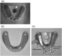
An acrylic resin mandibular edentulous model (G1-402; Nissin, Kyoto, Japan) was modified for use in the experiments (Figure 1(a)). Two implants (Standard RN, Straumann AG, Basel, Switzerland) were inserted in the canine region on both sides of the edentulous residual ridge, perpendicular to the occlusal plane of the experimental IOD. An artificial mucosa made using a silicone impression material (ExaFlex Injection-type, GC, Tokyo, Japan), approximately 2-mm thick,16⇓–18 was affixed to the edentulous molar area, posterior to the two supporting implants of the mandibular model (Figure 1(a)). A film pressure distribution measurement tactile sensor was placed on the artificial mucosa on the right side (Figure 1(a)). The artificial mucosa was molded by initially fixing the film sensor to the basal surface of the experimental IOD, followed by polymerizing the silicone under the application of a 5-N load to the occlusal surface of the IOD.
Experimental model and denture: (a) experimental model, (b) experimental denture, and (c) sensor setting condition.
The experimental IOD was made using acrylic resin (Acron MC, GC) for the denture base material (Figure 1(b)). The basic form of the experimental IOD was a ready-made record base with an occlusal rim (Na-N4, Nissin). The occlusal table of the denture was fabricated parallel to the occlusal plane.
Devices for simultaneous measurement of three-dimensional (3D) loads on the supporting implants and the load on the residual ridge beneath the denture base were developed. Piezoelectric force transducers (Type Z18400; Kistler Instruments AG, Winterthur, Switzerland)20⇓–22 were used to measure the loads on the implants. A film pressure distribution measurement tactile sensor (I-SCAN, Nitta, Osaka, Japan)23 was also used to evaluate the load on the residual ridge.
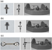
To measure the load on the implants, three types of attachments were fabricated to be fitted accurately onto the piezoelectric force transducers: a ball-type attachment (BA), a locator-type attachment (LA), and a round-bar-type attachment (RA) (Figure 2). The male part of BA, which has the same form as an anchor abutment (Straumann AG), was manufactured using a high-precision processing technology to be fitted accurately onto the piezoelectric force transducer, whereby the inferior portion was configured to fit the superior end of the implant. LA, which has the same form as a locator abutment (Zest Anchors Inc., Escondido, CA, USA), was also manufactured to be fitted accurately onto the piezoelectric force transducer. Additionally, the length of the screw part of both BA and LA was configured to properly fit into our measuring device. For the female parts of these attachments, an elliptical matrix (Straumann AG) was used in BA, and pink-colored extended range replacements (Zest Anchors Inc.) were used in LA. The male part of RA was made of the the male round bar (Male part P3, Cendres & Metaux SA, Bern, Switzerland) and a specific titanium coping, which was manufactured to be fitted accurately onto the piezoelectric force transducer. An adjustable rider (Cendres & Metaux SA) was used as the female part for RA.
Load measurement experiment
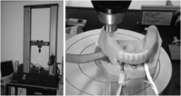
Loads on the implants and the residual ridge beneath the denture base were measured when static and dynamic repeated loads of 100 N were applied vertically to the right first molar region of the occlusal table of the denture by a universal testing machine (Instron 5685; Instron, Norwood, MA, USA) (Figure 3). The load measurement was repeated five times for each of the three different attachments in the order BA, LA, and RA.
Experimental loading device.
Loading device: the universal testing machine (Instron 5685, Instron).
First, the male part of BA was attached to the implant and the female part was embedded in the denture base using quick cure resin material (Pattern Resin, GC) under application of a 5-N load to the occlusal surface of the IOD. After the BA measurements were taken, the male and female parts of BA were removed, and then the male part of LA was attached to the implant and the female part was embedded into the denture base in the same manner as for BA. Finally, after the LA measurements were taken, the male and female parts of LA were removed, and then the male part of RA was attached to the implant and the female part of RA was embedded into the denture base. The female parts of BA and RA were used with a default setting for retentive force.
A static load of 100 N, which was assumed to be the occlusal force, was applied to the right first molar area on the occlusal surface of the denture at a crosshead speed of 15 mm/s and continued for 10 s. A dynamic repeated load of 100 N, which was used to simulate a masticatory force, was applied to the same area at a crosshead speed of 30 mm/s and a loading cycle of 2 Hz. Each loading condition was repeated five times under the same attachment. The load was applied in a direction perpendicular to the occlusal surface. The contact area between the model and the fitting surface of the denture was exclusively set at the attachment and on the artificial mucosal area.
Analysis
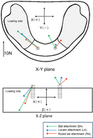
Measured 3D loads on the implants were analyzed using a 3D coordinate. The Z-axis was vertical direction, which was defined to be perpendicular to the occlusal surface of the denture, that is, the same in the implant inserted direction. The X-axis was lateral and Y-axis was antero-posterior direction. The X- and Y-axes were defined to be coincident with the occlusal surface of the IOD (Figure 4). The measured pressure on the residual ridge beneath the denture was converted to a force and analyzed as the total force on the measurement area.
Statistical analysis was undertaken using IBM SPSS Statistics for Windows Version 21.0 (IBM Corp., New York, NY, USA). One-way analysis of variance was employed to compare results among the three experimental attachments, after which Bonferroni correction was used as a post-hoc test.
Results
Load on the supporting implants
Figure 4 shows the maximum load vectors displayed at the 3D coordinates when a static load of 100 N was applied. Regardless of the attachment type, the direction of the load exerted on both implants was consistently in a posterior direction. The force vector on the nonloading side implant for the three attachments occurred in an upward direction.
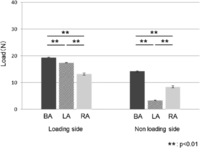
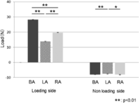
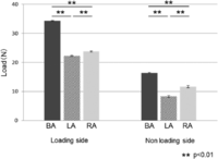
The horizontal component, that is, the resultant force value of the load on the implants in the X- and Y-axes when a static load of 100 N was applied, was significantly highest on the loading side in BA, followed by LA, and RA (p < 0.01) (Figure 5). On the nonloading side, the resultant force value was significantly highest in BA, followed by RA, and LA (p < 0.01). The vertical component of the load on the loading side was significantly highest in BA, followed by RA, and LA when a static load of 100 N was applied (p < 0.01). However, although LA was significantly lowest on the nonloading side, there was little difference among the three attachments (Figure 6). Figure 7 shows the resultant force values on the implants in 3D when a static load of 100 N was applied. The load in BA was significantly highest, followed by RA and LA both on the loading and on the nonloading sides (p < 0.01).
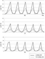
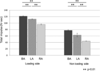
Figure 8 shows an example of the calculated 3D resultant force data for the three attachments when a dynamic repeated load of 100 N was applied five times. The three attachments showed different wave patterns. BA and RA exhibited a plateau phase between the peaks of the waves, but this was not evident in LA on the loading side implant. Figure 9 shows the total impulse of the load on the implants, which was calculated based on the load data shown in Figure 8. The total impulse in BA was significantly highest, followed by LA and RA on both the loading and nonloading sides (p < 0.01).
Load on the residual ridge beneath the denture base
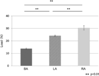
Figure 10 shows the load on the residual ridge beneath the denture base when a static load of 100 N was applied. The load was highest for RA, followed by LA and BA (p < 0.01).
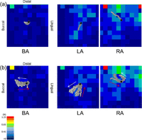
Figure 11 shows the typical pattern of load distribution on the residual ridge beneath the denture under a static and dynamic repeated load of 100 N. With all of the attachments, a higher load was exerted in the distal parts of the sensor area. The shifting pattern of the load center on the residual ridge is shown in Figure 11. Although the load centers of the three attachments were in a similar position, the loci of the load center were different among the three attachments.
Distribution of load on the residual ridge beneath the denture: (a) during the static 100 N of load being applied (n = 5) and (b) during the dynamic 100 N of load being applied (n = 5).
Black point: load center when the maximum load was exerted.
Gray dot: a shifting pattern of load center.
Red arrow: load applying phase.
White arrow: load disengaging phase.
Discussion
It is essential to understand the load on implants supporting the overdenture and the load on residual ridge beneath the denture base during function for preventing the technical complications and obtaining the longitudinal good outcome.6⇓⇓⇓⇓⇓–12 The measurement of 3D loads on implants supporting overdentures was pioneered by Mericske-Stern et al.,13 who developed an in vivo 3D load measuring device using piezoelectric transducers. However, the effect of attachment system on the 3D loads on implant supporting overdenture and the residual ridge beneath the denture base has been still unclear. This study aimed to clarify those loads in detail.
Recently Goto et al.18 revealed the influence of the attachment installation conditions on the load transfer to the implants supporting the overdenture and denture movements using a load-cell transducer in a model experiment. They showed that the load on the implant with a BA was greater than that with a LA or a magnet attachment when those attachments were installed under a loading of more than 50 N on the denture. In the present study, the load on the implants in BA was similarly highest under both static and dynamic repeated loads, although the applied load of installing the attachments into the denture base was 5 N. In previous studies, the BA was found to provide a highly retentive force.24,25 However, the different heights of the three attachments (see Figure 2) might have affected the 3D loads on the implants in this experimental condition.
When the load was applied to the loading point on the denture, the denture base settled down. At this time, the denture was thought to rotate on the Y–Z plane as well as on the X–Z plane (see Figure 4). The direction of the load on the loading side implant thus was consistently lateral (right) and posterior regardless of the attachment type. These finds correspond to the previous in vivo studies.14
On the other hand, the direction of the load on the nonloading side implant was upward (Figure 6). As a result of the rotational movement of the denture, the retentive force against the rotational movement was supposed to be generated on the nonloading side implant. However, the lateral direction of the load on the nonloading side implant was different among the three attachments. In particular, that with RA faced left side, which was the nonloading side direction. In RA, the implants were splinted with bar unlike other two attachments, which was believed to affect the load direction on nonloading side implant.19,26,27
When the dynamic repeated load was applied, the plateau phases between the peaks of the waves were not evident in LA on the loading side implant. Because the LA has a particular mechanical interlocking and frictional contacts, which was a combination of external and internal joints24 compared with the other two attachments, the inherent looseness in LA was supposed to be smaller than that in the other two attachments. As for the total impulse on implants, that in RA was the smallest, which might mean that the total functional loads on implants during mastication in RA can be smaller than those in LA and BA. As the total impulse can lead to an increase in the stress or strain in the bone around implants, these data should be helpful for research in this area.
The load on the residual ridge beneath the denture was greatest in RA, followed by LA and BA. This result is consistent with a previous report using finite element (FE) analysis.28,29 In the previous report, the bone remodeling activity beneath the denture base of the mandibular IOD was predominantly shown in the molar region.30 In addition, the recent FE analysis showed that the load on the residual ridge affected the hydrostatic stress in the mucosa which led to the bone resorption beneath the denture base.31 Therefore, the bone resorption might be prone to occurring beneath the denture base of the IOD with RA.
As shown in the shifting pattern of the load center within the sensor area on the residual ridge (see Figure 11), it mainly changed the lateral direction in BA and RA, which were thought to be affected by the rotational movement of the denture as above mentioned. The incidence of mucosal complication such as a decubitis ulcer beneath the denture base of IOD with the resilient attachment might be related to that rotational movement.2,9 On the other hand, the load center of LA mainly changed in the antero-posterior direction. In this study, new female parts were used in all attachments. Because Rutkunas et al.32 showed the high initial retentive force of LA, the rotational movement of the denture with LA was considered to be unlikely occurred, and the deflection of the denture base with a fulcrum of the LA on the loading side implant might be preferentially occurred. This could also explain the reason of smallest load on nonloading side implant in LA. However, denture movement is affected not only by the attachment system but also by other factors, such as the form of the residual ridge, tissue displacement, and the position of the implants. Thus, further investigation is necessary to clarify these factors. One point of view is that to prevent deflection of the denture base, a LA might be inappropriate for edentulous patients whose mucosa is significantly displaced by forces in the edentulous area.
In this study, the measuring device using a tactile sheet sensor enabled us to measure the load distribution on an area of approximately 100 mm2 of the residual ridge. However, the sheet sensor was still not large enough to evaluate the load on the whole area of the residual ridge. In terms of the pressure distribution, there is also the possibility that a large amount of the load was exerted on the posterior mucosal area beyond the sheet sensor for every attachment. Nevertheless, for clinical use of the bar attachment, the denture base should be designed to be as large as possible to withstand the occlusal force on the residual ridge.
Conclusion
The limited conclusions drawn from the results of this study were as follows:
-
This model experiment using piezoelectric 3D force transducers and a tactile sheet sensor enabled us to clarify the effects of the attachments used in an IOD on loading to implants and the underlying residual ridge.
-
Using RA in an IOD is effective for reducing the load to the supporting implants.
-
The load on the residual ridge beneath the denture in IODs can be efficiently reduced using a BA.
Article Notes
-
Declaration of conflicting interests The authors declare that there is no conflict of interest.
-
Funding This work was supported by Grants-in-Aid for scientific research from the Ministry of Education, Culture, Sports, Science and Technology (MEXT), Japan (23592833).
- Received December 5, 2014.
- Accepted February 10, 2015.
- © The Author(s) 2015
This article is distributed under the terms of the Creative Commons Attribution-NonCommercial 3.0 License (http://www.creativecommons.org/licenses/by-nc/3.0/) which permits non-commercial use, reproduction and distribution of the work without further permission provided the original work is attributed as specified on the SAGE and Open Access page (http://www.uk.sagepub.com/aboutus/openaccess.htm).

